Spanning-tree protocol (STP) is one of those network technologies that is easy to forget about. It exists in the background of almost every network, and for the most part it does it’s job without any issues. However, there is still a huge benefit to understanding what STP does and how it works - because it’s default behaviors might not the the best for every network.
I’ve been making progress going through my CCIE books, and the earlier sections are focusing on layer 1 and layer 2 technologies. A lot of this is review from CCNP studies, but with STP the book starts to get into additional detail on the inner workings of the protocol - which I’m finding to be quite fascinating. It seems like in many of the companies that I’ve worked I’ve found that a majority of the IT staff (whether sysadmins or network admins) don’t really have a good handle on how STP works and why it needs to be tuned. So this post is meant to cover spanning-tree at a very high level, and I’ll include some examples from issues I’ve seen in the past.
So what is spanning-tree protocol anyways?
At it’s very basic level, STP is a communications protocol used between switches to allow them to identify redundant paths in the network. The goal of STP is to figure out what is the most efficient L2 path through the network, then block all other paths to prevent loops. The best way I’ve heard STP explained is that it’s essentially a routing protocol for layer 2. Rather than routers communicating and exchanging routes to determine the best path through a network, all of the switches will talk to determine the best (loop-free) layer 2 path.
STP determines the best layer 2 path - but the best path to what?
When configuring a standard routing protocol (like EIGRP or OSPF), you might have a node that advertises a route for 10.10.10.0/24. All other routers in the network are going to select a best path to the router who originates this advertisement - but how does something like this work when we’re talking about layer 2?
Spanning-tree relies on the concept of having a single root bridge of each network. At the beginning of a spanning-tree process, all switches will hold a quick election to determine who the root bridge is - then each switch will figure out what it’s own best path is to that device. The switch that ultimately becomes the root bridge will be based on the priority set by the administrator - but by default all switches are pre-configured with the same priority. In a tie, the switch with the lowest MAC address will win and become the root bridge.
What does that actually mean? More or less, one switch gets put in charge of defining the best path through the network. All other switches examine all of their redundant paths to the primary switch, then figure out which of those paths are more preferable than the others. An important note here, is that the “best path” selected is all from the specific viewpoint of whichever switch takes charge.
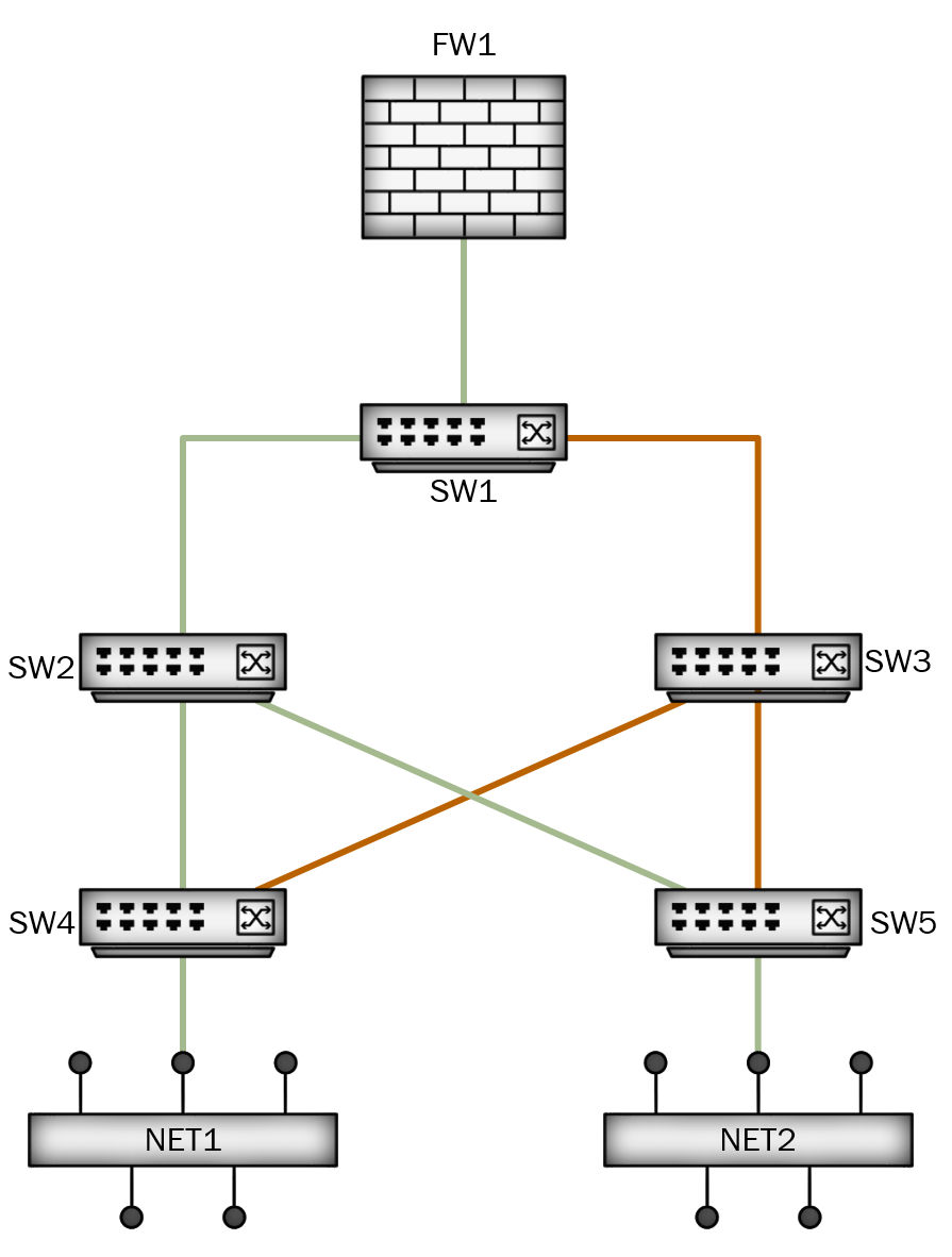
For an example, let’s use the following topology:

In this example, we have five switches and a firewall - which are used to provide connectivity to two network segments (NET1 and NET2). For each of the two network segments, there are a number of different paths that traffic could take to reach the firewall. Without spanning tree, NET1 might send traffic to SW4, which in turn would forward it to both SW2 and SW3. This sounds like a good thing, since we would use all available paths to try and reach the firewall - but in reality this can cause other problems like the firewall receiving packets out of order.
So for the example above, let’s assume that SW1 becomes our root bridge. SW1 is now in charge of determining what the best path through the network is. It does this by sending out messages on all ports connected to other switches, called Bridge Protocol Data Units (BPDU). In this message, SW1 asserts it’s role as the root bridge - and provides some information for other switches to use for path selection. Each switch will examine the message from SW1 to determine which of it’s uplinks is the most efficient path to SW1. Once each switch does this, it will forward on the message to downstream switches - this time adding in some of it’s own information (or path cost).
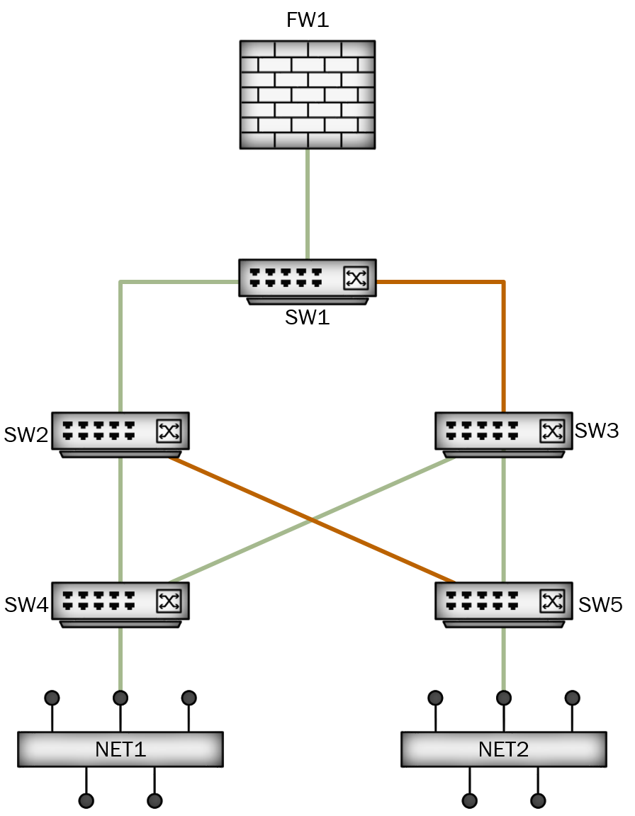
After all that is complete, we might be left with the following path below:
The green lines above show the final path that was selected. For NET1 to reach the firewall, it would use SW4, then SW2, then up to SW1. For NET2, it would use SW5 > SW2 > SW1. This leaves the orange links unused. In fact, spanning-tree will place these links into a blocking state. The switches might still listen on those links, just in case their neighbor starts advertising a better path - but they will not forward any data traffic on these connections. In the case of SW2 suddenly failing, SW4 and SW5 would still be aware of their connections through SW3 - and after a brief period would begin using those links to reach the firewall.
This is a very simplistic explanation, and there is a lot more in the background that actually happens during spanning-tree operation. There are a number of different STP standards that a switch can run, each with their own options for configuration and tuning. There are also methods of providing a loop-free path while still utilizing some redundant paths. I plan to cover some more detail on these topics in later posts.
So why should I care about STP?
Remember that part earlier when I said that if STP priority is not configured, then switch with the lowest MAC becomes the root bridge? Well as it turns out, MAC addresses are the hardware addresses configured by the manufacturer - and these addresses increment as they produce new devices. So the lower MAC addresses are typically going to be the oldest equipment in your network. Unfortunately, this can have a dramatic effect on your network traffic if you’re not paying attention to STP.
From the earlier example, what happened if SW4 became the root bridge? Maybe this was an old Cisco 2950 that someone forgot to replace and it’s just been left in the network. If the STP configuration went unmodified, then this switch would likely become the root bridge of our network. Let’s look at what that path might look like:
So in this case, SW4’s path to the firewall hasn’t changed. However, it’s best path to SW5 and NET2 is through SW3 - which means any traffic from NET2 to the firewall has to follow the path of SW5 > SW3 > SW4 > SW2 > SW1. Not only does that add more layer 2 hops that NET2 has to pass through, but it also adds more (unnecessary) load onto SW4. What happened if SW4 was so old that it still had 100M ports? It might get overwhelmed pretty quickly.
Now you might be thinking, “How often does this really happen”? Well, when I started at my last job they were experiencing a similar issue. The primary building had three floors, each with two Cisco 3548 switches to service users. Each of these switches linked back to a pair of Cisco 4500 core switches. All of the 3548 switches were purchased at the same time (far prior to the 4500s), and it turned out that one of them on the third floor had the lowest MAC address in the network. The entire layer 2 topology was then based on this switch as the central point of the network. This caused the interconnects between the core switches to be put into blocking mode - meaning that if a switch on the second floor needed to connect to the alternate core switch, then it would have to pass traffic through the third floor. A quick change to the spanning-tree priority (during a maintenance period) was all that was needed to put the core switches back in charge.
This doesn’t immediately make spanning-tree a bad technology. As with just about anything in IT, it’s something you need to understand and tune to fit your needs - otherwise you’ll just get less-than-ideal results. At another employer, I actually found out that the previous network administrator had manually disabled all of the redundant paths in the network - because he didn’t understand STP, and therefore thought that any redundant paths would cause a loop. Spanning-tree isn’t something we need to be afraid of - it just needs a little attention.
So next time you’re logged into one of the switches in your network, just run show spanning-tree and double-check that the switch you assume is your root bridge actually is.
Well I hope that this was helpful. As I mentioned earlier, I meant this as a fairly basic overview - but I intend on diving a bit deeper in later posts. The most fascinating part of networking to me is all the details on how things like spanning-tree actually work behind the scenes. Have any spanning-tree stories? Leave a comment below
